• Language
  • VEBKO

  • Introducing the Company and Products
    • Assembling Stages of AMT105 Tester
    • Disperesing Stages of AMT Tester
    • Introducing the Device and Equipment
    • Comparative Analysis of AMT105, AMT205, AMT103, and AMT203 Devices
    • AMPro Software Translation
  • Software Installation and Connection Setting
    • Software Installation
    • How to Connect to AMT
    • Simultaneous Connection of Several Testers
    • Resetting IP Address
    • Updating Firmware of Device Manually
  • Default Setting
    • General Setting of Rooms
    • General Setting of Rooms, Part2
    • Default Setting for “Report”
    • Preferences Page "Directory" & "Cash" Tab
    • "Connection & Firmware"Tab
    • Device Hardware Setting
    • Modifying and Improving the Translation of the Vebko Amirkabir Company Website
    • Power Control and Its Relation to Heat
    • Modifying and Improving AMPro Software Translation
  • Software Home Page
    • General Types of Rooms
    • Software Start Page
  • Modules Toolbar and Statusbar
    • Toolbar and Status Bar, Part 1
    • Toolbar and Status Bar, Part 2
    • “New Based on Custom Template” Option
    • Determining Decimal Numbers, Part 1
    • Determining Decimal Numbers Part 2
    • Analog Output Setting
    • Binary Input Setting, Part1
    • Binary Input Setting, Part2
    • Binary Output’S Setting
    • Extra Setting
    • Relay Specification in Test Object
    • Introducing the “RIO”
    • Introducing “XRIO”
    • XRIO Converter File
    • XRIO Converter, Part2
    • Complementary Explanation About “XRIO Converter”
    • XRIO and XRIO Converter
    • XRIO & Relay Setting in the Software
    • XRIO Converter Formula Writing
    • Writing “XRIO Converter” for an Overcurrent Relay
    • Writing Formula for the “XRIO Converter” 3
    • Writing Formula for “XRIO Converter”4
    • Writing Formula for “XRIO Converter”5
    • Complementary Explanations of “Device” Section
  • AMT Sequencer Module
    • An Introduction to the Sequencer Room
    • “Table View” Window
    • The Separate Toolbar of “Table View” Window
    • “Detail View” Tab
    • Analog Out Tab
    • Quick Type
    • Step Ramp Type
    • Continuous Ramp Type
    • Harmonic State
    • The “Transient” State Type:
    • The “Transient” State (Observing the Impedance Trajectory)
    • The "Transient" State (Observing the Differential Trajectory)
    • “Tracking” State
    • "Set Mode and Fault Type" : Part 1
    • "Set Mode and Fault Type" : Part 2
    • Additional Settings of “Detail View”
    • "Signal View" Window Part 1
    • “Signal View” Window, Part 2
    • “Signal View” Setting, Part 1
    • “Signal View” Setting, Part 2
    • ”Vector View” Window, Part 1
    • “Vector View” Window, Part 2
    • “Vector View” Window, Part 3
    • “Measurement View” Window, Part1
    • “Level Assessment” Tab
    • “Ramp Assessment” Tab
    • “Value Assessment” Tab
    • “Calculated Assessment” Tab
    • "Transient Assessment" Tab
    • Running the Test
    • Start-Condition-Repetition" Window
    • “Report Setting” Window
    • “Report View” Window
    • Advanced Settings of “Report” Part 1
    • Advanced Settings of “Report” Part 2
    • Abilty to Convert Output Binary Voltage to Current and Vice Versa
    • Sampled Value
  • AMT Overcurrent Module
    • Introducing Over Current Room
    • Relay Settings in the "Overcurrent" Room – Part 1
    • Relay Settings in the "Overcurrent" Room – Part 2
    • Relay Settings in “Overcurrent” Room, Part 3
    • Relay Settings in the "Overcurrent" Room – Part 4
    • Test View Window
    • “Pick Up-Drop Off” Window
    • “Overcurrent” Characteristic Curve
    • “Settings” Tab of “Overcurrent” Module, Part 1
    • “Settings” Tab of “Overcurrent” Module, Part 2
    • Directional Earth Fault
    • Complementary Explanation of “Overcurrent” Room
    • Directional Overcurrent
  • AMT VI STARTING Module
    • Introducing “VI Starting” Room
    • “Shot Test” Tab
    • “Check Test” Tab
    • "VI Starting" Room Setting
  • AMT Distance Module
    • Introducing “Distance” Room, Part 1
    • Introducing “Distance” Room, Part 2
    • Introducing “Distance” Room, Part 3
    • Introducing “Testview” Window in “Distance” Room, Part 1
    • “Check Test” Tab
    • “Search Test” Tab
    • “Distance” Room Settings, Part 1
    • “Distance” Room Settings, Part 2
    • Impedance View Window
    • “Zt Diagram” and “Medium Detail View” Windows
    • Grounding Factor in Distance
    • Distance Protection Voltage and Current Calculations in the Test Room
  • AMT Differential Module
    • Relay Settings in “Differential” Room, Part 1
    • Relay Settings in “Differential” Room, Part 2
    • Introducing “Test View” Window in “Differential” Room, Part 1
    • Introducing “Test View” Window in “Differential” Room, Part 2
    • “Differential” Room Settings
    • “Differential Characteristic” Window
    • No Combined Characteristic
    • Zero Sequence Elimination
    • Restricted Earth Fault
  • AMT Diff Harmonics Module
    • Introducing “AMT Diff. Harmonics” Room
    • “Test View” Window
    • “Setting” Tab
    • “Harmonic Restraint View” Window
  • AMT Transducer Module
    • “Offload” Test Part 1
    • “Offload” Test Part 2
    • “Onload” Test of the Meter
    • Transducer Test
    • How to Use the Optical Pulse Sensor in Meter Testing
  • AMT Synchronizer Module
    • An Introduction to AMT Synchronizer
    • Test View Window in Synchronizer Room
  • AMT VCC Room
    • AMT VCC Room
  • Current Transformer Module
    • Introducing “Current Transformer (CT)” Room
    • Secondary Burden Test
    • Winding Resistance Test
    • “Excitation Test” Tab, Part 1
    • “Excitation Test” Tab, Part 2
    • CT “Excitation Test”, Part 3
    • CT Excitation Test, Part 4
    • Other Tests Performable in “Excitation Test” Tab
    • CT Ratio and Polarity Test with Current Method
    • CT Ratio and Polarity Test (with Voltage)
    • CT Test Wiring Guide Using the Instrument Module
    • CT and PT Turns Ratio
    • Estimating FS and ALF for Various CTs
  • Circuit Breaker Module
    • Introducing “Circuit Breaker(CB)” Room
    • CB “Timing Test”
    • “Contact Resistance” Tab
    • Circuit Breaker Operation Minimum Voltage Test:
    • A Guide for Performing CB Test Connections Using the Instrument Module
  • capacitor voltage transformer
    • Capacitive Voltage Transformers
    • Secondary Burden Test
    • Short-Circuit Impedance Tab
    • Winding Resistance Test
    • Excitation Tab
    • CVT Ratio2
    • Ratio Tab
    • A Guide for Cvt Test Wiring Using the Instrument Module
  • Transformer Module
    • Introducing “Transformer” Room
    • “Vector Group, Turns Ratio and No Load” Tab
    • “Magnetic Balance” Tab
    • “Winding Resistance” Tab
    • “Leakage Reactance“ Tab
    • “Demagnitize” Tab
    • Guide to Performing Transformer Test Using Instrument Module
    • Zero Sequence Elimination
    • How to Use Clamps in Transformer Testing
  • OverCurrent Quick Test Room
    • Overcurrent Quick Test Room
  • Under OverVoltage Test Room
    • Under Over Voltage Test Room
  • AMT AR Room
    • AMT Ar Room
  • Resistance Test
    • Resistance Test
  • Troubleshooting
    • The Complete Main Switching
    • Main Switching Error Overcurrent Board
    • Overcurrent Error of Board 2 Part 1
    • Overcurrent Error Board 2 Part2
    • Switching Troubleshooting
    • OC Board IGBT Test
    • Introducing the Internal Modules Part1
    • Introduceing Internal Modules Part2
    • Introducing Internal Modules Part3
    • Switching Module
    • Possible Errors in the Switching Module
    • Checking the Parts,in Switching Module Errors Part1
    • Checking the Parts,in Switching Module Errors Part2
    • Checking the Parts,in Switching Module Errors Part3
    • The Connections Between the Switching Module and the Amplifier
  • Testing of relays protection functions
    • End-to-End Test
    • Overvoltage Protection Function Test in MICOM P141 Relay
    • Undervoltage Protection Function Test in MICOM P141 Relay
    • Directional Overcurrent Protection Function Test in MICOM P141 Relay
    • Directional Earth Fault (DEF) Protection Function Test in MICOM P141 Relay
    • New End-to-End Test
    • Drawing the Distance Characteristics and Practical Example of Drawing the Quad Characteristic in Siemens 7SA522 Relay
    • Drawing the Load Encroachment Characteristic
    • Drawing the Mho Characteristic in GEC PYTC Relay
    • Synchronizer Function Test in SIPROTEC Siemens 7SD82 Relay
    • 51V Function Test in Siemens 7SD82 Relay
    • Non-Directional Overcurrent Protection Test in AMR Relay (Simple Test Using Templates)
    • Under Voltage Protection Test in AMR Relay (Simple Test Using Templates)
    • Overvoltage Protection Test in AMR Relay (Simple Test Using Templates)
    • Negative Sequence Overcurrent Protection Test in AMR Relay (Simple Test Using Templates)
    • Directional Overcurrent Protection Test in AMR Relay (Simple Test Using Templates)
    • Non-Directional Overcurrent Protection Test in AMR Relay (Simple Test Using Templates)
    • Distance Protection Test in AMR Relay (Simple Test Using Templates)
    • Differential Protection Test in AMR Relay (Simple Test Using Templates)
    • Rogowski Coil Test
  • ZA
  • Goose Messaging Testing
    • GOOSE Messaging Testing
  • Trust the Software
    • Guide to Trusting Vebko(Stable-Test) Software in Bitdefender Antivirus
    • Guide to Trusting Vebko(Stable-Test) Software in Kaspersky Antivirus
    • Guide to Trusting Vebko(Stable-Test) Software in NOD32 Antivirus
  • PMU Test
    • PMU Test
  • ZE
  • Introdusing Company and Produces
    • Assembly Stages of AMR Relay
  • Software Download and Installation
    • Software Installation
  • Software Homepage and Create Project
    • Login to the Main Environment of the Software
  • Connection and Update Firmware
    • Connect with Relay
    • Firmware Relay Update
  • Relay Hardware
    • Relay Hardware Module
    • Voltage and Current Transformers Data
  • AMR Relay Test
    • Differential Protection Test in AMR Relay (Simple Test Using Templates)
    • Directional Overcurrent Protection Test in AMR Relay (Simple Test Using Templates)
    • Negative Sequence Overcurrent Protection Test in AMR Relay (Simple Test Using Templates)
    • Distance Protection Test in AMR Relay (Simple Test Using Templates)
    • Non-Directional Overcurrent Protection Test in AMR Relay (Simple Test Using Templates)
    • Overvoltage Protection Test in AMR Relay (Simple Test Using Templates)
    • Under Voltage Protection Test in AMR Relay (Simple Test Using Templates)
  • Real Testing Requires Realistic Signals
  • AMPro Protocol Sniffer
  • Meet SV100+
  • IEC 61850 Sampled Values Testing
  • Digital substations run at the speed of light
  • Don’t Just Test Your Relays. Simulate the Grid
  • Smart Configuration Inheritance in VCC — With Full Control
  • Control What Appears in Your Test Report
  • From Comtrade to Inject
  • Design and Navigate Complex Test Procedures with the AMPRO Sequencer
  • One State. Four Transitions. Total Control
  • Stop waiting for the test to finish
  • Balanced System, Zero Trip, Infinite Confidence
  • Defining Complex Logic For Assessments
  • Advanced Assessments
  • Vebko Around The World
  • Noise Suppression in Transformer Turns Ratio
  • Relay Data in Quick Access
  • Wiring Clarity - Without Leaving Your Workspace
  • Design and Navigate Complex Test Procedures with the AMPRO Sequencer
  • Flexible Connectivity with AMT205 in AMPRO
  • Simultaneous Ramp on All Outputs [AMT205]
  • Continuous Ramp Capability [AMT205]
  • Distance Search Testing
  • Comprehensive Circuit Breaker Testing [AMT205]
  • Smarter Configuration In VCC File
  • New Feature In Vebko AMPro
  • Vebko Educational Videos
  • Contact Resistance Measurement
  • Test With Confidence
  • Control Your Report
  • One Device, Any Relay
  • DC Resistance Measurement
  • History of Amt105 GPS
  • History of Amt105 Wifi
  • AMT 105 Features
  • Catalog
    • Catalog All
    • Accessories
    • Agencies
    • Catalog
    • Hardware
  • 26.03.21
    🚀 Smarter Test Management with VCC Files in Vebko AMPRO
    
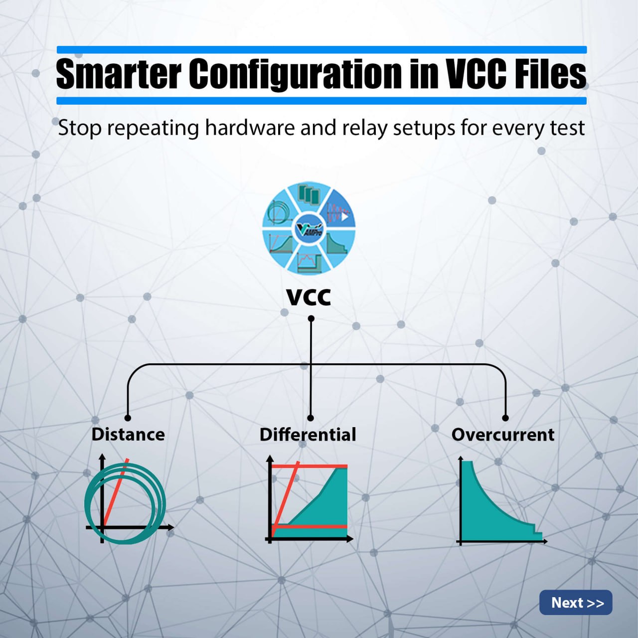
    When working with VCC (Vebko Control Center) files in Vebko AMPRO, a single file can include multiple test modules such as:
    ✔ Overcurrent
    ✔ Differential
    ✔ Distance
    ✔ Quick Tests
    ✔ And more…
    — all typically designed for protection relay testing.
    ----------------------------------------------------------------------
    ⚙️ The Challenge
    For each test, two critical configurations are required:
    🔹 Hardware Configuration (HC)
    Defines how the test device is wired (voltage/current outputs, binary/analog inputs)
    🔹 Relay Configuration (Test Object)
    Includes relay settings such as nominal values, XRIO files, and other parameters
    👉 When multiple test modules exist in one VCC file, repeating these configurations becomes time-consuming and inefficient.
    ----------------------------------------------------------------------
    💡 The Solution: Inherit Feature in AMPRO
    With the Inherit capability, you can:
    ✔ Define a Hardware Configuration once and reuse it across multiple tests
    ✔ Create multiple HC profiles and assign them flexibly
    ✔ Apply the same approach to Test Object and Report Settings
    ----------------------------------------------------------------------
    🔗 What Can Be Inherited?
    Test files inside a VCC can inherit:
    • Hardware Configuration (HC)
    • Test Object
    • Report Settings
    ✅ Result:
    Less repetitive work, faster setup, and consistent configuration across all tests
    ----------------------------------------------------------------------
    🚀 Coming Soon
    We are introducing an advanced feature where:
    ➡️ Test Objects can inherit from other Test Objects
    This enables:
    ✔ More flexible configuration structures
    ✔ Advanced parameter management
    ✔ Even greater efficiency in complex testing scenarios
    #Vebko #AMPRO #RelayTesting #ProtectionTesting #PowerSystems #SubstationAutomation #EngineeringSoftware #PowerEngineering
    LinkedIn Website
    photo 2026 04 01 10 56 01 (2)
    photo_2026-04-01_10-56-01 (2)
    photo 2026 04 01 10 56 01
    photo_2026-04-01_10-56-01
    VEBKO LinkedIn Post
    Publish Date: —

    Smarter Configuration In VCC File

    Post Type Technical Post
    Topic AMPRO / Relay
    Company VEBKO

    Post Media

    Media

    LinkedIn Caption

    Content

    Tags / Hashtags

    SEO

    LinkedIn Actions

    Links
    Open LinkedIn Post Visit VEBKO Website
    Use this section for the final post link, website link, or any landing page related to the campaign.

    Contact / CTA

    Sales
    Mr. Mostafa Hajati
    International Technical Marketing Director
    [email protected]
    [email protected]
    +90 501 367 3174
    Ms. Golchehreh
    International Sales & Communication Officer
    [email protected]
    +90 551 997 6983
    Website: http://vebko.org
    © 2026 Vebko. All rights reserved.

    Related topics

    • Smart Configuration Inheritance in VCC — With Full Control
    • New Feature In Vebko AMPro
    • AMT VCC Room AMT VCC Room
    • Control What Appears in Your Test Report
    • Defining Complex Logic For Assessments
    • Login to the Main Environment of the Software Software Homepage and Create Project
    • IEC 61850 Sampled Values Testing
    • Software Start Page Software Home Page